This document is included in the Canon iR2200/2800/3300 service manual for the product concerned and serves as a reference, giving the distributors a good understanding of the product in advance. Most of the contents of this document are not official, and therefore free, before the product is brought, make it important to take into account that the descriptions are only true from the date on the cover. The document "Information about new products" replaces the Trainer manual (TR) most They are familiar with and is the result of our efforts to provide for all useful information Offices in every sales company. Most of the contents of this document are not official and are therefore subject to change Change before the product is placed, so it is important to take into account that The descriptions are true only from the date indicated on the cover. In the service manual for the product, descriptions of the changes will be updated. The problem may have occurred. Please make sure this document is correct Should be disposed of as soon as it is available in the Service Manual.
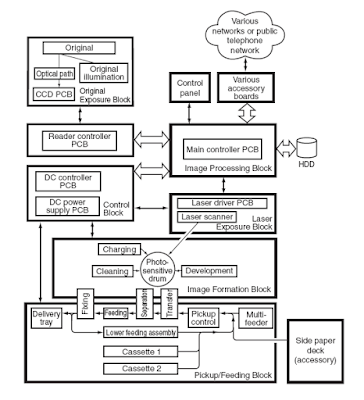
Outline of Operations; The reader controller PCB is used to read the image signals from the CCD read and send picture Signals to the main controller assembly. The video signals from the main controller assembly Are converted by the DC controller PCB into laser drive signals and are used to laser Intensity signals signal level from the laser driver PCB. The laser strength signals are used to produce the laser beam a laser beam that causes the laser beam Is directed to the photosensitive drum for the formation of latent static images. The laser beam also serves to create blank exposure image areas.
Generating Sync Signals; The BD signal used to synchronize the video signals in laser scanning direction is generated Through the BD-PCB with respect to the laser mounted by the BD mirror reflected beam in The path of the laser beam. Paper edge newly selected in double-sided mode is detected by the horizontal registration. Sensor for measuring the displacement to the rear / front. Based on the measurement of the Time of activation of the laser is changed with respect to the BD signal, so the picture becomes At a certain position on the paper.
Table of contents Canon iR2200/2800/3300 Service Manual
- General Description
- Original Exposure System
- Laser Exposure System
- Image Formation System
- Pickup/Feeding System
- Fixing System
- Externals And Controls
- Paper Deck
Download Canon iR2200/2800/3300 Service Manual here

0 Response to "Canon iR2200/2800/3300 Service Manual"
Post a Comment